Rev. Sci. Inst., 1993, 64(2), 529-31DOI:
10.1063/1.1144227
Modification of a commercial microwave oven for applications in the chemical laboratoryM. A. B. Pougnet
Department of Chemistry, University of Cape Town, Rondebosch, 7700, Republic of South Africa
(Received 11 September 1992; accepted for publication 5 October 1992)
A commercial microwave oven has been modified for laboratory applications. The modifications include the lining of the cavity with polypropylene, the use of a polypropylene turntable, incorporation of inlet and outlet ports, and the use of an extraction system to purge the oven’s cavity.
I. INTRODUCTIONAfter a long history of microwave processing in industry and the use of microwave ovens in the home, the first report on a chemical laboratory application using microwaves appeared in 1974, when a microwave oven was used to dry small samples.’ This was followed by a publication concerning microwave sample dissolution using mineral acids (digestion).’ Since then the number of reports on laboratory sample preparation and other uses, such as for organic and organometallic synthesis, has grown tremendously. j-7 Earlier work was carried out in commercial ovens designed for kitchen use with few or no modifications and several shortcomings were apparent. This led to many investigations into the development of suitable equipment to carry out the chemistry safely and efficiently. The first commercial microwave moisture analyzer oven became available in 1981 and an oven for sample digestion in 1985. Today there are several manufacturers of laboratory ovens. Specially designed microwave transparent pressure vessels for sample digestion are also available from several suppliers. The cost of these laboratory ovens is relatively high and many laboratories are using domestic ovens. Perhaps the most important problem in using these in laboratories is the high degree of corrosion when using mineral acids that can lead to malfunction of the units, excessive microwave leakages, and electrical fires. Furthermore, when working with volatile organic solvents, vapors can be sucked back in the power supply compartment where the occurrence of a spark could also lead to a dangerous situation. In this report, the modifications to a commercial microwave oven to make it safe for laboratory applications are described.
II. MICROWAVE OVENAfter investigating the suitability of several available microwave ovens for the modification, the SHARP model R-lOR50 INVERTER oven was chosen. This oven was selected for the following characteristics: robust construction and stainless steel cavity; relatively large cavity size to accommodate the lining (see below) and a wide variety of available pressure vessels; efficient cooling of the magnetrons and adequate overheat protection; easy programming of several heating steps (power/time); and the excellent power control that is available through the use of two 500-W magnetrons (total available power of 1 kW) and a state-of-the-art INVERTER circuit that allows power levels to be adjusted in 10% increments. The desired power is set in watts and is continuous at the different levels as compared to pulsed operation of the magnetron in most ovens. In this system, only one of the magnetrons is used for power settings of less than 500 W and the power delivered by this magnetron is controlled by the inverter circuit. For larger power settings, the latter is controlled and the second magnetron operates at full power. The output power calibration of the oven is shown in Fig. 1. Excellent linear and reproducible calibration is obtained for 1- and 2-l water loads. The advantage of this system for laboratory applications, where small loads are normally used, is that lower power levels can be used which minimizes the amount of reflected power reaching the magnetrons. Results obtained for the heating of small volumes of water at different power levels is shown in Fig. 2. A dummy load of 100 ml of water was placed in the cavity during the tests and the positions of the test loads were kept as constant as possible. The apparent absorption of power for the different loads (reproducible to within a few percent) illustrates the “antenna” effect that is related to the shape and size of the object in relation to the electromagnetic field in the cavity. Adequate heating rates are achieved for small loads of water, mineral acids of relatively low boiling points, and polar organic solvents. Because of small volumes of solvents normally used in laboratory applications, a dummy load ( - 100 ml water) is
normally included. The latter is not found to affect the reproducibility of heating of the samples.
III. MODlFlCATlONSThe oven as purchased is fitted with grill, convection, and rotisserie facilities. These components were removed and their electrical connections terminated. The cavity lamp was removed. The standard turntable motor was replaced with a stronger geared motor capable of turning a load of 8 kg at 5 rpm. To accommodate the larger motor, the legs of the oven were raised by 10 cm. A polypropylene lining (10 mm thick) was fitted inside the cavity with an indented section to allow the normal flow of air from the cooling of the magnetrons to the air outlet section (Fig. 3). The front of the lining was sealed to the cavity with silicone compound and the stainless steel front of the cavity was treated with several layers of PTFE coatings (Nr.438, A. W. Chersterton Co., USA).

FIG. 1. Output power calibration.

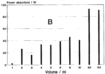
FIG. 2. (a) Temperature increase for 20-s irradiation of water loads.
(b) Calculated power absorbed for 20-s irradiation of water loads at 300 W.
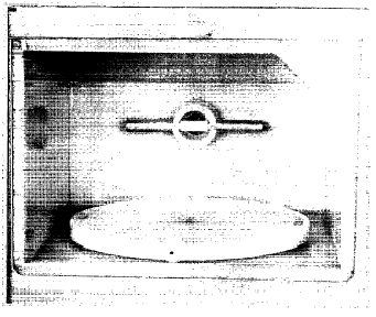
FIG. 3. Polypropylene lining of the cavity. The mounting of the gas tube in front of the air inlet port is visible at the back of the cavity.
Two stainless-steel ports (41.3 mm i.d., 130 mm long) were fitted to the cavity (visible in Fig. 4) by bolted double flanges. One at the back of the cavity serves as an air inlet and one on the lhs as the outlet. The ports are lined with polypropylene and provide a completely plastic connection between the lining and the extraction system (see below). This design was used to offer a free-flow system, thus preventing changes of the velocity and avoiding condensation, as often occurs with perforated ports. A filter is fitted to the air inlet port. The extraction system is connected to the outlet port through a flexible 32-mm PVC hose. The extraction system comprises a high-speed fan and operates by a venturi effect (Fig. 5). Thus no corrosive fumes can reach the motor/fan. This system provides a high extraction rate of greater than five cavity volume changes per minute and is completely demountable for cleaning. The outlet of the extraction system is routed outside the laboratory or to a laboratory fume hood.
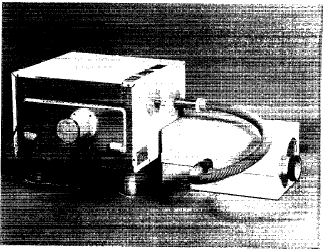
FIG. 4. Inlet port and filter at the back of the oven and the outlet port connected to the extraction system. The small port is also visible on the side of the oven.

FIG. 5. The extraction system. The venturi nozzle section can be disconnected from the larger tube containing the electric motor for cleaning.
A small stainless steel port (15.8 mm i.d., 80 mm long) lined with polypropylene was fitted for using fiber optic temperature measurement devices, pressure lines, for flushing gases through the cavity, or for special extraction purposes. The standard turntable was replaced by a 15-mm thick polypropylene one fitted with wheels. This turns on the polypropylene bottom of the cavity lining. The mass of the relatively heavy pressure vessels therefore does not rest on the gearbox of the motor. The standard lamp was ineffective through the thick polypropylene lining. A small fluorescent lamp as is used for caravan lighting ( 130 mm long) was used instead. Direct ionization of the gas in the lamp is achieved even at low powers. The problem of using such tubes is that they get very hot, especially at the metal caps, and cracking of the glass occurs. This problem was dealt with by inserting the two ends of the tube in stainless-steel tubes and exposing only about 30 mm of the tube’s center portion and placing this in front of the inlet port where the flow of air keeps the tube cool. This device is simple and offers a bright light and can be inserted when visual observation is required.
By means of current sensing circuitry in the extraction fan motor and a relay placed in the oven’s power input line, the operation of the oven is not possible without proper functioning of the extraction system. This precaution was deemed necessary for complete protection in laboratory applications.
IV. DISCUSSIONThe modified oven was tested for microwave leakages. Levels were below the 1 mW/cm’ specified by legislation for new equipment ( < 5 mW/cm2 in use). The polypropylene lining structure showed slight deformation after several weeks of intensive use, but the basic shape and function was not affected. The extraction system was found to provide sufficient flow to deal with acid fumes released from venting valves of pressure vessels and boiling off of organics. No condensation was noted within the cavity or in the extraction system. The system has been successfully installed in our laboratory for over a year and has been used extensively for sample digestion using a wide range of pressure vessels and mineral acids, for drying of samples, and for reactivation of silica gel and molecular sieve containing organic solvents.
ACKNOWLEDGMENTSResearch grants from the University of Cape Town and the Foundation for Research and Development (FRD) are greatly appreciated. The author thanks A. I. Chalef, K. Achleitner, and D. W. M. Lensen for their technical inputs.
1. J. A. Hesek and R. C. Wilson, Anal. Chem. 46, 1160 (1974).
2. Abu-Samra, J. S. Morris, and S. R. Koirtyohann, Anal. Chem. 47, 1475 (1975).
3. H. M. Kingston and L. B. Jassie, Introduction to Microwave Sample Preparation, Theory and Practice, ACS Professional Reference Book, Washington ( 1988).
4. H. Matusiewicz and R. E. Sturgeon, Prog. Analyt. Spectrosc. 12, 21 (1989).
5. MM. A. B. Pougnet, ChemSA 284 (1989).
6. R. Gedye, F. Smith, and K. Westaway, J. Microwave Power Electromagnet. Energy 26, 4 (1991).
7. D. M. P. Mingos and D. R. Baghurst, Chem. Sot. Rev. 20, 1 (1991).