


The following are instructions on building an overhead stirrer from parts you may have lying around, or which can easily be acquired for next to nothing. The heart of the stirrer is a stepper motor—also easily available.
Stepper motors can be found in a lot of old computer hardware. Printers, floppy drives, scanners all have them. They look like small electric motors but have four or more wires coming out of them. The only constraint is that you need one with four wires, and that’s essential. The motors in hard drives (unless they’re ancient) aren’t steppers and can’t be used.
Note that this stirrer will have no speed control, but the force can be controlled by the shape of the stirrer blade. A larger stir blade will do more than a small one. Torque is pretty good, and should suffice for most purposes. When choosing or making the blade, make sure it’s going to fit into the container you want to stir.
Parts List
• Stepper Motor
• 2” piece of braided nylon hose
• Large capacitor – not the kind in a cylindrical metal can. These are usually shaped as a round, flattened ceramic disk, sometimes rectangular with rounded corners, and usually have two leads. There are really no other electronic components that look like this, so you can be fairly sure you have the right thing if they fit the description. Yellow, orange and blue are the most common colors. Get the largest in size that you can find, and don’t try to use tiny ones—they won’t work. You may need to use two. Capacitors can be found in virtually every electronic circuit. Those found in an old monitor, microwave, stereo or computer power supply should be good.
• Glass or metal rod, depending on your application. Metal allows a large stirring paddle because it can be made to fold up next to the rod. The disadvantages of metal are obvious. The disadvantage of glass is that it would be difficult to make the paddle fold up.
• Support hardware – whatever you can cobble together. For the prototype a flat piece of aluminum was attached to a clamp from a kids scooter that allows the motor to be conveniently raised an lowered on a stand. See Figure 2.
• Transformer (wall wart) rated at approximately 12 VAC. You can probably get away with voltage as low as 6 and as high as 15. Find the label on the stepper motor if you can, to see the voltage rating. It’s not critical but try to match that, or come as close as you can. Higher voltage = more torque, but more heating of the motor.
AC transformers aren’t as common as DC, so read the label on the body to make sure you don’t use DC by mistake. If you can’t find an AC transformer you can modify one made for DC if you’re comfortable with electronics.
Equipment and supplies
• Ohm meter. Harbor Freight sells a digital multi-meter for $5, less when they’re on sale.
• Soldering iron, flux and solder, or small wire nuts.
• Electrical tape or shrink wrap.
Wall Wart Modification (Only needed if you can’t find one designed for AC.)
Unplug the unit and open it up. You will see wire attached to the wall plug going to a transformer. On the other side of the transformer there will be two copper wires coming out, attached to some electronic components. Cut these wires at a point before they reach the electronics. The wires may appear to be bare copper, but they are not. They’re coated with a hard plastic insulation that must be removed on roughly the last half-inch. That’s most easily done with a piece of sandpaper. Get it shiny bright or you’ll have trouble with the connections. Now attach an insulated wire to each of these connections. Solder them together or use a small wire nut. Insulate with electrical tape or shrink wrap.
The Wiring The wiring is easy. With an ohmmeter, check the wires coming out of the stepper motor. There are two pairs where one wire is connected to the other. You need to identify the pairs. We’ll call one pair the 1st pair and the other the 2nd. (Flip a coin to decide which is which, but label them once you decide.) In Figure 1 the top two wires coming from the stepper have been designated the 1st pair. The third and forth are the 2nd. Notice that they originate from the same place, one wire leading to the second pair is connected through the capacitor. Insulate all the connections with electrical tape or shrink wrap.

Figure 1. Wiring
At this point you’re ready to test the circuit. Plug in the wall wart and the stepper motor should begin to turn. If it does not, the capacitor is probably connected to the wrong wire of the second pair, so swap them and try again.
If it still doesn’t turn you probably need a larger capacitor. If you don’t have one, add another in parallel with the first. Keep adding capacitors until the motor turns. (Don’t use tiny little ones or you may never get there.) Keep in mind that you still have to check after each attempt to ensure that the capacitor is connected to the correct wire in the second pair.
Once you’ve verified your wiring it’s time to mount the motor. Place it on top of the support to protect it from heat and fumes. You might want to build an enclosure of some sort, but make sure it’s got adequate ventilation.
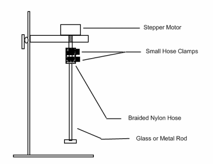
Figure 2. Example Mounting
Cheers,
PP
Edit:
As luck would have it I ran across the pictures I had of the prototype, so if I can figure out how to get them into this post you can see them. You may note that the prototype showed me a few problems that I fixed in the write up.
The first of these was mounting the motor under the support arm. This puts it in the path of heat and fumes, so it would be much better to have it on top of the bar, with a plate directly underneath to block whatever might drift up. (Stepper motors don't have brushes so there's not a fire risk, but they don't like too much heat or corrosive fumes.)
The other correction that comes to mind is the placement of the capacitor. This is a no-brainer and I don't know why I originally put it where it is. It should be back away from the stand and protected inside a container of some sort.
PP
Stepper motors can be found in a lot of old computer hardware. Printers, floppy drives, scanners all have them. They look like small electric motors but have four or more wires coming out of them. The only constraint is that you need one with four wires, and that’s essential. The motors in hard drives (unless they’re ancient) aren’t steppers and can’t be used.
Note that this stirrer will have no speed control, but the force can be controlled by the shape of the stirrer blade. A larger stir blade will do more than a small one. Torque is pretty good, and should suffice for most purposes. When choosing or making the blade, make sure it’s going to fit into the container you want to stir.
Parts List
• Stepper Motor
• 2” piece of braided nylon hose
• Large capacitor – not the kind in a cylindrical metal can. These are usually shaped as a round, flattened ceramic disk, sometimes rectangular with rounded corners, and usually have two leads. There are really no other electronic components that look like this, so you can be fairly sure you have the right thing if they fit the description. Yellow, orange and blue are the most common colors. Get the largest in size that you can find, and don’t try to use tiny ones—they won’t work. You may need to use two. Capacitors can be found in virtually every electronic circuit. Those found in an old monitor, microwave, stereo or computer power supply should be good.
• Glass or metal rod, depending on your application. Metal allows a large stirring paddle because it can be made to fold up next to the rod. The disadvantages of metal are obvious. The disadvantage of glass is that it would be difficult to make the paddle fold up.
• Support hardware – whatever you can cobble together. For the prototype a flat piece of aluminum was attached to a clamp from a kids scooter that allows the motor to be conveniently raised an lowered on a stand. See Figure 2.
• Transformer (wall wart) rated at approximately 12 VAC. You can probably get away with voltage as low as 6 and as high as 15. Find the label on the stepper motor if you can, to see the voltage rating. It’s not critical but try to match that, or come as close as you can. Higher voltage = more torque, but more heating of the motor.
AC transformers aren’t as common as DC, so read the label on the body to make sure you don’t use DC by mistake. If you can’t find an AC transformer you can modify one made for DC if you’re comfortable with electronics.
Equipment and supplies
• Ohm meter. Harbor Freight sells a digital multi-meter for $5, less when they’re on sale.
• Soldering iron, flux and solder, or small wire nuts.
• Electrical tape or shrink wrap.
Wall Wart Modification (Only needed if you can’t find one designed for AC.)
Unplug the unit and open it up. You will see wire attached to the wall plug going to a transformer. On the other side of the transformer there will be two copper wires coming out, attached to some electronic components. Cut these wires at a point before they reach the electronics. The wires may appear to be bare copper, but they are not. They’re coated with a hard plastic insulation that must be removed on roughly the last half-inch. That’s most easily done with a piece of sandpaper. Get it shiny bright or you’ll have trouble with the connections. Now attach an insulated wire to each of these connections. Solder them together or use a small wire nut. Insulate with electrical tape or shrink wrap.
The Wiring The wiring is easy. With an ohmmeter, check the wires coming out of the stepper motor. There are two pairs where one wire is connected to the other. You need to identify the pairs. We’ll call one pair the 1st pair and the other the 2nd. (Flip a coin to decide which is which, but label them once you decide.) In Figure 1 the top two wires coming from the stepper have been designated the 1st pair. The third and forth are the 2nd. Notice that they originate from the same place, one wire leading to the second pair is connected through the capacitor. Insulate all the connections with electrical tape or shrink wrap.
Figure 1. Wiring
At this point you’re ready to test the circuit. Plug in the wall wart and the stepper motor should begin to turn. If it does not, the capacitor is probably connected to the wrong wire of the second pair, so swap them and try again.
If it still doesn’t turn you probably need a larger capacitor. If you don’t have one, add another in parallel with the first. Keep adding capacitors until the motor turns. (Don’t use tiny little ones or you may never get there.) Keep in mind that you still have to check after each attempt to ensure that the capacitor is connected to the correct wire in the second pair.
Once you’ve verified your wiring it’s time to mount the motor. Place it on top of the support to protect it from heat and fumes. You might want to build an enclosure of some sort, but make sure it’s got adequate ventilation.
Figure 2. Example Mounting
Cheers,
PP
Edit:
As luck would have it I ran across the pictures I had of the prototype, so if I can figure out how to get them into this post you can see them. You may note that the prototype showed me a few problems that I fixed in the write up.
The first of these was mounting the motor under the support arm. This puts it in the path of heat and fumes, so it would be much better to have it on top of the bar, with a plate directly underneath to block whatever might drift up. (Stepper motors don't have brushes so there's not a fire risk, but they don't like too much heat or corrosive fumes.)
The other correction that comes to mind is the placement of the capacitor. This is a no-brainer and I don't know why I originally put it where it is. It should be back away from the stand and protected inside a container of some sort.
PP