


So I've already designed one for and ultrasonic humidifier...but im pretty sure It can be adapted to a coolmist setup.
Sorry about the messy post my images aren't loading correctly or I have too many or something...I will try and clean it up later
It costs about 100 dollars for materials and parts...but i have calculated that i can just leave my greenhouse for 2 months and not have to worry about it malfunctioning...
So here are a few diagrams showing how everything is set up.
(see attachments)
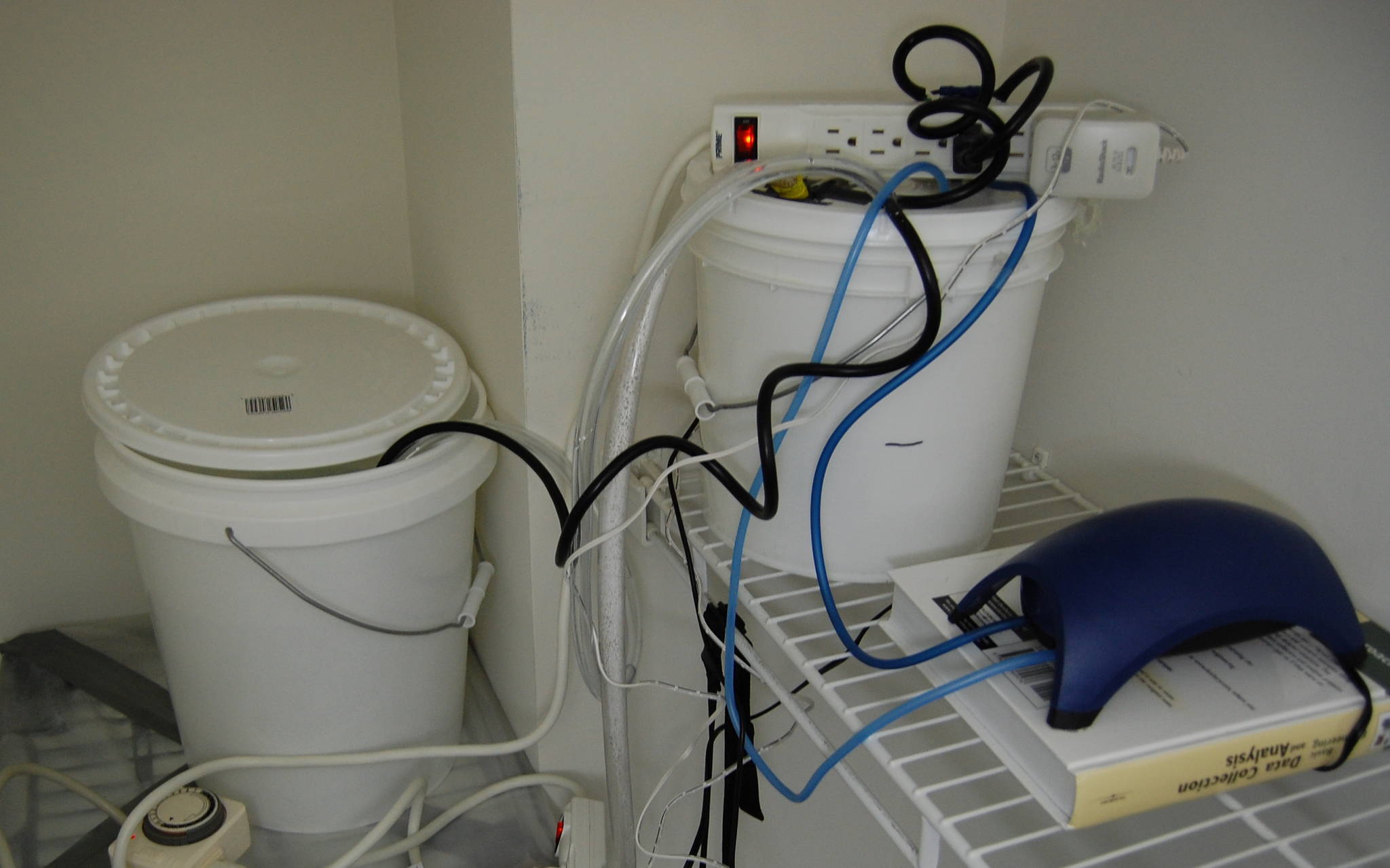
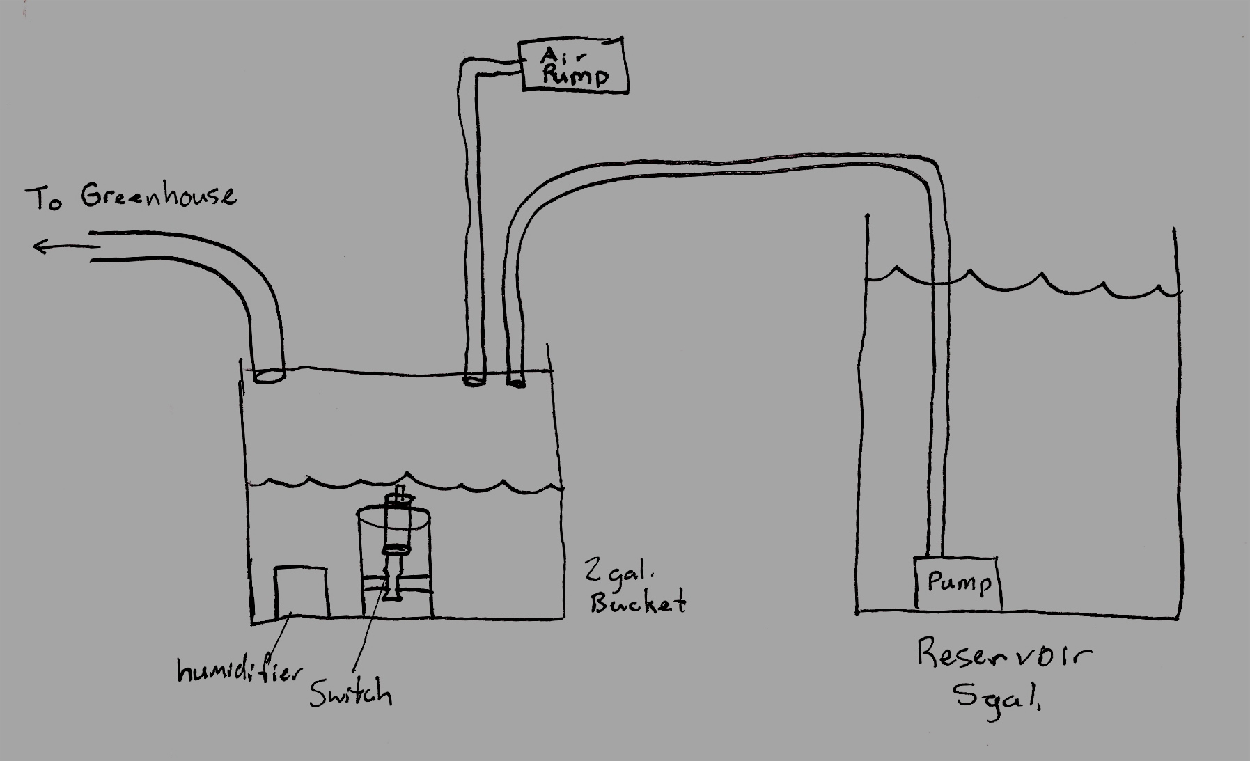
this is the basic humidifier with the auto-refill reservoir on the right.
(see attachments)
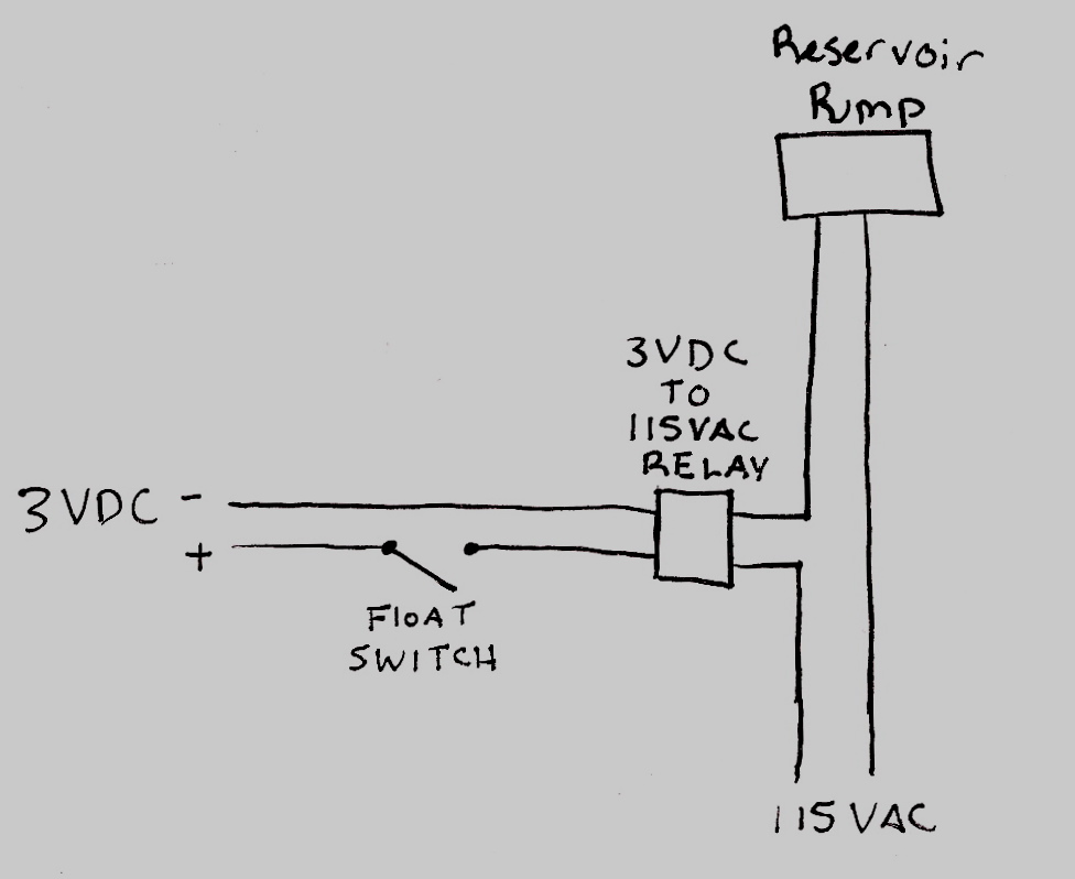
and this is the very simple wiring diagram of the refill circuit
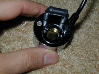
my humidifier setup uses a standard ultrasonic mister unit
these can be found and purchased easily for 20 dollars.
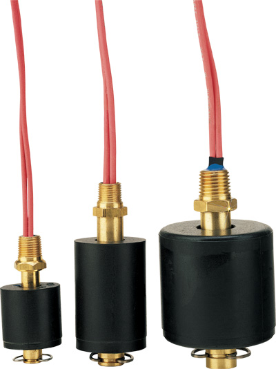
The two most important pieces are the float switch
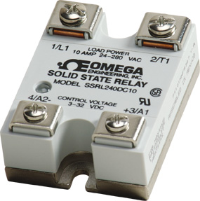
and the relay.
Just incase you haven't worked with relays before. They usually use a low voltage input signal (in this case 3 VDC) and when this circuit is closed i.e. voltage supplied to the relay, it closes another circuit that is usually of higher voltage (in this case 115 VAC or a standard US outlet).
So the layout is pretty simple once you test out the circuit with a multimeter to check for conductivity when the float switch is supposed to be closed and whatnot. For the 3VDC i used a cheap AC to DC power supply that you can get from radio shack. you can also choose what voltage DC you want (3,4.5,6,9, and 12). For the AC side of the relay i just spliced it into the power cord of the fountain pump.
I used a 105 GPH pump which is rated at 1 foot of head and has a max head pressure of 3 feet i believe. One needs to remember though, that the top level of the water in the reservoir needs to be below the level of the tube that drains into the humidifier bucket, or it can set up a siphon effect that can cause an overflow.
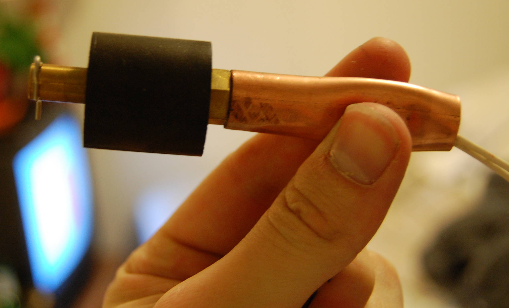
The biggest hurdle during the construction was how to mount the float switch inside the humidifier bucket and protect it from surface turbulence from the humidifier itself. After a little bit of thought i got some 3 inch PVC pipe and cut it to length so that it is short enough to fit inside the bucket when the lid is on. I then drilled 4 half inch holes in the sides of the tube about 1/4 inch from one end. I then filled the humidifier bucket to its operating level, and placed the float switch in the water until the float just hit the travel stop, then measured the distance between the bottom of the bucket and the top of the black float. I used that measurement to figure out where i needed to drill my 2 extra 1/2 inch holes in the PVC for the switch supports.
I cut a 2 inch long piece of 1/2 inch copper tubing and used expoxy to attach it to the bottom of the float switch,
then used a standard table vice to flatten a section of the tubing such that the supports on the PVC would attach to this flattened areas and hold the float in place at the proper level.
I could then attach these supports on the flattened areas using epoxy, and then fix the supports onto the PVC pipe using epoxy.
I threaded the wires through one of the 4 bottom holes and secured the PVC pipe to the bottom of the humidifier bucket using epoxy. Note that the end with the holes in it should be on the bottom.
Once this is done I drilled enough holes for the tube coming from the reservoir (3/8 inch tiagon tubing) and for the extra wires, as well as holes for the air hoses to go in, and another 3/8 inch outlet tube that carries the humid air to the greenhouse.
With my setup one can fill the reservoir with 5 gallons of distilled water and leave it for up to 3 months and not have to worry about refilling, and with an ultrasonic humidifier, which has an auto shut-off, even if it does run out, you dont have to worry about it burning up or anything. The fountain motor i purchased can also run steady in no water for 30 days without burning up the bearings.
Sorry about the messy post my images aren't loading correctly or I have too many or something...I will try and clean it up later
It costs about 100 dollars for materials and parts...but i have calculated that i can just leave my greenhouse for 2 months and not have to worry about it malfunctioning...
So here are a few diagrams showing how everything is set up.
(see attachments)
this is the basic humidifier with the auto-refill reservoir on the right.
(see attachments)
and this is the very simple wiring diagram of the refill circuit
my humidifier setup uses a standard ultrasonic mister unit
these can be found and purchased easily for 20 dollars.
The two most important pieces are the float switch
and the relay.
Just incase you haven't worked with relays before. They usually use a low voltage input signal (in this case 3 VDC) and when this circuit is closed i.e. voltage supplied to the relay, it closes another circuit that is usually of higher voltage (in this case 115 VAC or a standard US outlet).
So the layout is pretty simple once you test out the circuit with a multimeter to check for conductivity when the float switch is supposed to be closed and whatnot. For the 3VDC i used a cheap AC to DC power supply that you can get from radio shack. you can also choose what voltage DC you want (3,4.5,6,9, and 12). For the AC side of the relay i just spliced it into the power cord of the fountain pump.
I used a 105 GPH pump which is rated at 1 foot of head and has a max head pressure of 3 feet i believe. One needs to remember though, that the top level of the water in the reservoir needs to be below the level of the tube that drains into the humidifier bucket, or it can set up a siphon effect that can cause an overflow.
The biggest hurdle during the construction was how to mount the float switch inside the humidifier bucket and protect it from surface turbulence from the humidifier itself. After a little bit of thought i got some 3 inch PVC pipe and cut it to length so that it is short enough to fit inside the bucket when the lid is on. I then drilled 4 half inch holes in the sides of the tube about 1/4 inch from one end. I then filled the humidifier bucket to its operating level, and placed the float switch in the water until the float just hit the travel stop, then measured the distance between the bottom of the bucket and the top of the black float. I used that measurement to figure out where i needed to drill my 2 extra 1/2 inch holes in the PVC for the switch supports.
I cut a 2 inch long piece of 1/2 inch copper tubing and used expoxy to attach it to the bottom of the float switch,
then used a standard table vice to flatten a section of the tubing such that the supports on the PVC would attach to this flattened areas and hold the float in place at the proper level.
I could then attach these supports on the flattened areas using epoxy, and then fix the supports onto the PVC pipe using epoxy.
I threaded the wires through one of the 4 bottom holes and secured the PVC pipe to the bottom of the humidifier bucket using epoxy. Note that the end with the holes in it should be on the bottom.
Once this is done I drilled enough holes for the tube coming from the reservoir (3/8 inch tiagon tubing) and for the extra wires, as well as holes for the air hoses to go in, and another 3/8 inch outlet tube that carries the humid air to the greenhouse.
With my setup one can fill the reservoir with 5 gallons of distilled water and leave it for up to 3 months and not have to worry about refilling, and with an ultrasonic humidifier, which has an auto shut-off, even if it does run out, you dont have to worry about it burning up or anything. The fountain motor i purchased can also run steady in no water for 30 days without burning up the bearings.