


DIY Hotplate With Magnetic Stirrer
These are instructions for building a hotplate with magnetic stirrer. Depending upon scrounging abilities it can be made from 100% ghetto parts at no cost. Realistically it’s going to be easier for most people to buy the required electric pan from a thrift store for $2-5 and a couple different types of blow dryers for about $4. It will cost another buck or two for a transformer and as maybe $3 for a potentiometer. I’ll assume you can find the magnet and a switch for free. You can buy alnico magnets from many online dealers, one of which is http://scientificsonline.com/product.asp_Q_pn_E_3060131. Be sure that what you order has the poles at the ends. Switches are available at Radio Shack, probably magnets too..
Anyone who wants to give it a try should be able to succeed with these instructions...
Parts List
* Electric pan with thermostat dial on cord
* Permanent magnet electric motor
* Alnico magnet, bar or cylinder with poles at the ends.
* Potentiometer, 100 Ohms, linear taper (Electronics parts store ~ $5 or less)
* Transformer--wall wart type—7.5VDC seems to work well, but anything between 5 and 10VDC should be fine.
* Switch—almost anything will do. Technically a Single Pole Single Throw (SPST) is the one designed for the job, but use what you can find.
Assembly Instructions
Choose the right motor. You will need to use a permanent magnet motor because there are no brushes to create to ignite fumes from something you’re cooking, and because speed control is easy.. They will usually be found in devices that run on AC current, but they work fine with DC.
To make sure a motor is brushless, you should be able to look through holes in the casing and see the sides of a curved magnet attached to the wall of the frame, and not coils of wire. Note that there will be wire coiled around the armature, which goes through the center of the assembly, which is fine. If you see the outer wires you probably don’t have the right type of motor. Another test is to start it up and look through holes in the casing for sparks. It’s no good if you see them. Electric hair dryers are usually good sources for the motors and sell for a couple of dollars at thrift stores.
Forget about using a computer fan. You need a strong magnet, and it will pull on the magnets inside the motor and make it difficult or impossible to start, and reducing the voltage to decrease the stirring rate may cause the motor to stall. In addition rare earth magnets from a hard drive will permanently lose most of their magnetism as soon as they get warm.
Test the motor. You should wire up and try out your motor before you assemble it, because it may not be possible to get it to turn slowly enough to be useful. (See the last section of this paper for wiring instructions.) Most of these motors are capable of spinning at a rate at least 100 times faster than you would ever want it to go, and some will stall out before they turn slowly enough to work for our purposes. If it happens to you use a slightly larger motor. Fortunately that’s the exception, and good motors aren’t hard to find.
Modifications. If the motor hadn’t come with the fan, a large flat washer or something of the sort would have been attached in it’s place. Whatever is used, it must be firmly secured to the shaft coming out of the motor, and balanced so it doesn’t vibrate.
On top of the fan or substitute, epoxy an alnico magnet like the one in the picture. It has to be alnico because it needs to be powerful—the stronger the better. You can’t use rare earth magnets like those in computer hard drives because they loose their magnetism after just a few minutes exposure to heat.
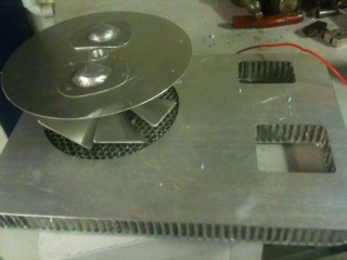
The prototype. Figure 1 shows an early prototype with a permanent magnet motor clamped between two pieces of aluminum to support it, and bolted to a rough, heavier piece of aluminum underneath. The black plastic piece at the top was the blower for the hair dryer which was already attached to the motor...It’s main purpose now is to provide a flat surface on which to mount the magnet, but it also creates air circulation that keeps the motor cool. This unit has been in use for over four years without any problems, and the fan is probably the main reason why.
In a later model the bottom plate has been replaced with a smaller, flat piece of aluminum, and the cylinder supporting the motor was replaced with steel from an old computer case. The steel does not interfere with the magnet at all, and was much easier to work with than thick aluminum.
Although it wasn't done at the time the pictures were taken, you will naturally want to mount the switch and the potentiometer on a plate of some sort.
Figure 1: Mounting the motor
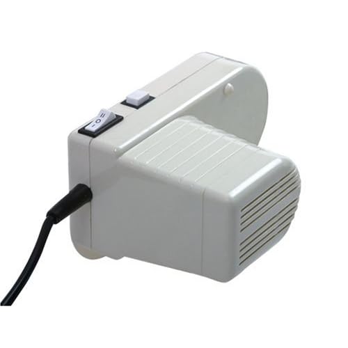
Selecting a hotplate. The other essential part is the hotplate. For this you need any one of a variety of cooking devices with the heating element embedded in a ring under the bottom of the pan. (See figure 2 for an example.) These cookers are almost always made of thick aluminum. Another common feature is an adjustable thermostat that plugs into the side of the device, and these tend to be more accurate than other types. Choose one that has a temperature range compatible with your needs. There are a large selection of grills, baked potato cookers, fondue pots, etc., which are common in thrift shops, most of which will work fine.
Wiring. You can see the purple wires leaving the motor on the left in Figure 1. Extend the wires when you mount the motor. If you forget you might have to take it back apart later.
Figure 2. The underside.
Motor Support And Alignment. The hotplate needs to be kept close to the magnet and centered under it. You want to have the magnet come as close to the bottom of the pan as possible without touching it, (this one comes within 1/8”). Because magnetism drops off quickly with distance this is important so you can stir thick liquids. The support needs to fit the bottom of the pan on the inside of the heating element and needs to be centered—you won’t want to have to move your flask to the side of the pan to stir. The final alignment must make the pan level.
The material used for the support shown is 1/8” aluminum, and once formed it was riveted to hold the shape. Cutting it was a pain because of the thickness but it’s strong and works well. The holes in the support are a good idea to keep your motor from getting too hot. If the material you choose doesn’t have any it would be a good idea to drill some.
Figure 3. Motor inside support.
Holding it together. This may challenge your imagination, but you’ve got to find a way to hold all of this together. Shown is one possible solution. The steel strip was riveted to the bottom of the support, and clamped under the pan handles. This worked well because the handles just happened to have enough room underneath for the strip. Whatever you use, it must be strong. Having the assembly collapse during use could be inconvenient.
Figure 4. Attaching the hotplate to the base.
Electrical Connections. The connections are simple. Just follow the diagram in Figure 5. The 10K pot is shown looking down on it from the top. It will have three connectors, but you only use two, and one of them needs to be on the center. If your stirrer speeds up when the knob is turned left and slows down when turned right, remove the wire on pin 1 of the pot and connect it to pin 3...
If you have the ability all electrical connections should be soldered and wrapped with heat shrink. If you can’t solder use small wire nuts from the hardware store. If you can’t use wire nuts twist the wires together and tape them. This is liable to cause trouble with bad connections before too long.
Be sure to insulate all exposed wire and connectors. Use shrink wrap if you have it, otherwise electrical tape.
Figure 5. Wiring diagram.
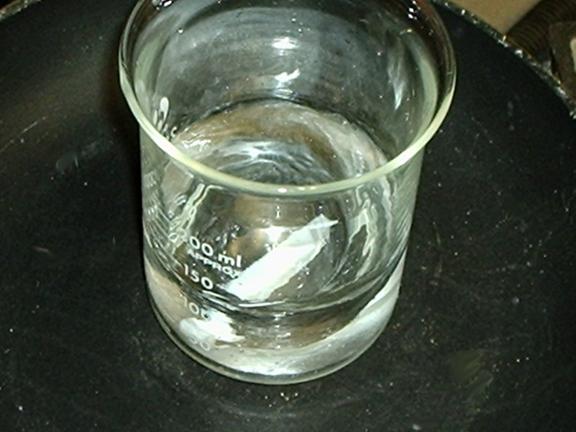
Does it work?
Figure 6. In action, normal speed.
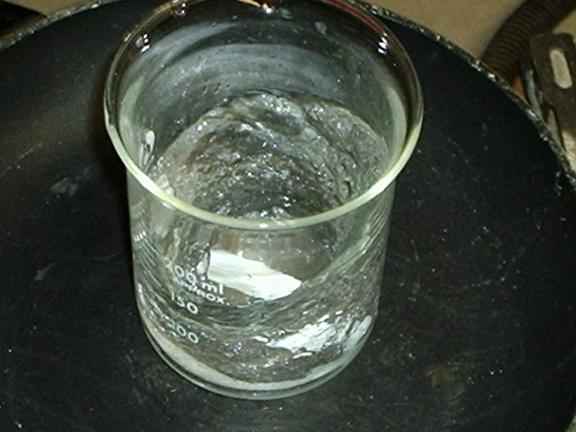
Figure 7. A little faster, but nowhere near max.